
Your boat vibrates strangely or grinds during acceleration? That’s your propeller shaft asking for help. Most marine mechanics won’t say this upfront: replacing a boat propeller shaft isn’t rocket science. But it does need precision and the right approach.
I’ve helped dozens of boat owners with this job. The ones who succeed have one thing in common. They don’t rush. They respect how marine drive shaft systems work step by step.
Maybe you have a worn cutlass bearing. Or a misaligned coupling. Or a corroded stern tube. This guide breaks down the full replacement into clear steps. You’ll save $800-$2,000 in shop fees.
You’ll learn which tools are worth buying. You’ll see how to measure shaft runout the right way. And you’ll understand why proper alignment makes your repair last two seasons or twenty.
No fluff here. No assuming you know the basics. Just a clear guide to help you tackle this essential maintenance task with confidence.
Propeller Shaft vs Propeller: Know the Difference

Many boat owners mix up these two parts. They work together, so the confusion makes sense. But getting them wrong during maintenance wastes your time and money.
The propeller shaft is a metal rod (solid or hollow) that runs from your engine to the back of your boat. It spins and sends torque through the water. Think of it as a delivery system—a mechanical pipeline that carries rotational power.
The propeller is the blade part bolted onto the shaft’s end. This is what converts spinning motion into forward thrust.
Here’s what sets them apart:
|
Component |
What It Does |
Complexity Level |
|---|---|---|
|
Propeller Shaft |
Sends engine torque through multiple sections (thrust, intermediate, tail shaft); handles misalignment and vibration |
Needs professional replacement |
|
Propeller |
Converts rotation into thrust using angled blades |
You can swap it yourself |
The shaft takes brutal mechanical stress. It absorbs engine thrust forces. It makes up for hull flex. It stays aligned through tapered or split couplings. Tapered designs give you bigger contact areas. They handle more torque too. That’s why serious marine drives use them.
Your propeller? Much simpler. Unbolt the hub nut. Slide it off. Match the pitch on your replacement. Torque it down per spec. Done.
Why this matters for replacement: Swapping a damaged prop takes an afternoon. You just need basic wrenches. Replacing the shaft? That’s different. You’ll dismantle couplings. You’ll realign multiple sections. You’ll seal the stern tube. You’ll balance for resonance. That’s specialist work. Don’t try shaft replacement without proper alignment tools and marine know-how.
Signs Your Boat Propeller Shaft Needs Replacement

A healthy shaft runs silent. A failing one announces itself through your feet, your steering wheel, and your wallet.
The Vibration Detective Work
That rhythmic thumping you feel—once per propeller revolution—points to a bent shaft. Count the beats against your RPM gauge. High-frequency buzzing? Your cutlass bearing needs retirement. Deep rumbling tells a different story: coupling sections aren’t aligned.
Watch for the weird pattern. Vibration kicks in at 1200 RPM. Disappears at 1500 RPM. Returns at 2000 RPM. That’s harmonic resonance. Your shaft flexes at certain speeds. This makes the problem bigger through your entire hull.
The Wiggle Test That Tells All
Kill your engine. Grab the propeller blade with both hands. Shake it hard—up, down, side to side. Feel anything move? Measure that play.
Movement under 1/16 inch (1.6mm)? Borderline. Keep monitoring. Visible wobble or an audible thunk above 1/8 inch (3mm)? Your cutlass bearing is toast. This play gets worse fast with throttle. A minor wiggle at the dock becomes violent shaking at cruising speed.
What Your Dial Indicator Reveals
Professional measurement beats guesswork. Mount a dial indicator on your shaft. Rotate it by hand. A bent shaft shows 0.004 inches (0.1mm) of runout—hard to see but important.
Anything exceeding 0.005 inches (0.127mm) needs action. Straightening works for minor bends. But combine that runout with a worn bearing? You’re past the repair point. Replace the shaft.
The Bearing Wear Patterns
Pull your cutlass bearing for inspection. Grooves carved into the rubber? Peeling surfaces? Cracked or chewed edges? All need replacement.
Look closer at where the wear sits. Heavy wear on top at the forward end but bottom wear at the aft end? That means misalignment. Your shaft runs at an angle. This grinds the bearing unevenly. Fix this now or face faster damage.
Cost Analysis: DIY vs Professional Service
Professional shaft replacement costs $1,200-$3,500 at most marinas. This covers labor ($800-$2,000), parts ($200-$800), and alignment work. Your boat needs proper alignment to run smooth.
DIY looks cheaper on paper. You’ll spend $300-$600 on parts. That’s the shaft itself, new cutlass bearings, stern tube packing, and coupling hardware. But here’s where it gets tricky.
The hidden costs pile up fast:
-
Alignment tools: $150-$400 to buy or $50-$100/day to rent. You need feeler gauges, dial indicators, and shaft measurement tools. Skip these? Your “savings” turn into vibration damage within a season.
-
Specialty equipment: Bearing pullers, coupling spreaders, torque wrenches rated for marine specs. Another $200-$500 if you don’t own them.
-
Mistake insurance: One bad stern tube seal creates a $2,000+ emergency haul-out. Wrong coupling alignment destroys your cutlass bearing in weeks. That’s another $400-$600 repair you’ll pay twice.
Most DIYers guess material costs too low by 20-30%. That $500 budget jumps to $650-$750. You need to buy extra supplies, replacement bolts, and parts you break during removal.
Time tells the real story. Pros finish in 6-10 hours. Your first try? Plan for 20-30 hours across multiple weekends. Value your time at $50/hour. That’s $1,000-$1,500 in lost time.
Go professional if you lack good alignment tools. Also use a pro for your first inboard shaft job. DIY makes sense if you’ve done marine drive work before. You should already own the key equipment.
Essential Tools and Equipment for Shaft Replacement
Skip the cheap toolkit. Marine shaft work destroys amateur gear within one job.
The Non-Negotiable Core Kit
Alignment measurement tools ($150-$400) stop vibration before it starts. You need feeler gauges in 0.001-inch steps and a dial indicator with magnetic base. Mount the indicator on your shaft. Rotate by hand. Read the shift at coupling faces. Anything over 0.005 inches? You need to realign. No guessing here.
Bearing removal equipment protects your stern tube. A three-jaw puller ($80-$120) grips cutlass bearing housings without breaking them. Heat the bearing first with a propane torch. 15 seconds, not 60. Heat breaks the rust seal. Then pull with steady pressure. Quick jerks crack the stern tube bronze.
Torque wrenches rated 150+ ft-lbs ($90-$180) lock your prop shaft coupling bolts to spec. Marine couplings need 140-165 ft-lbs. Shaft size decides the exact number. Too loose? You get play and wear. Too tight? The flange cracks. Click-type wrenches fail in saltwater. Beam-type tools stay true longer.
The Supporting Cast
Shaft seal installation tools ($40-$80) include drift punches sized to your packing gland. You’ll drive new flax packing or seals straight into the stern tube. Crooked seals leak within hours of launch.
Coupling spreaders and gap gauges ($60-$100) measure the gap between coupling halves. Standard spec runs 0.030-0.050 inches. Less causes binding. More causes poor alignment. Use real tools—not a screwdriver blade.
Penetrating oil, wire brushes, and rust breakers free decades of metal fusion. Soak coupling bolts 24 hours before removal. Bronze and stainless steel lock tight in saltwater. Forcing frozen bolts snaps the heads clean off.
Rent specialty items for one-time jobs. Buy quality hand tools you’ll use across multiple marine projects.
Pre-Replacement Prep and Check
Measure twice, remove once. That’s not just woodworking wisdom—it’s your wallet’s best friend for replacing a marine drive shaft.
Document Your Current Setup
Photograph everything before you touch a single bolt. Capture coupling positions from three angles. Mark the shaft-to-coupling orientation with a paint pen. Note which bolt holes align where. Your memory fails after pulling 40 fasteners. Photos don’t lie.
Measure your existing shaft diameter at three points: coupling end, mid-span, and propeller end. Write down the exact length from coupling face to prop nut seat. Taper specs matter. A standard 1:10 taper won’t fit a 1:12 coupling. Check your shaft material with a magnet. Stainless won’t stick. Bronze and Aquamet alloys will.
Secure Your Work Zone
Block your boat solid. Jack stands rated 2x your hull weight go under strong hull points. Not random spots that’ll crack. Chock both wheels on your trailer. A shifting boat mid-shaft-pull breaks bones. It breaks bronze fittings too.
Clear 6 feet of space behind your stern. You’ll slide that shaft straight out. No bends. No angles. Hitting a dock piling halfway through ruins your day and dents the shaft.
Gather Replacement Specs
Call your engine maker with your serial number. Ask for coupling bolt torque specs. Get shaft grade tips and tolerance ranges. Generic “marine shaft” orders fail. Taper angles must match. Order exact metals. Use 316 stainless in warm water. Use Aquamet 22 in cold saltwater.
Step-by-Step Propeller Shaft Removal Process
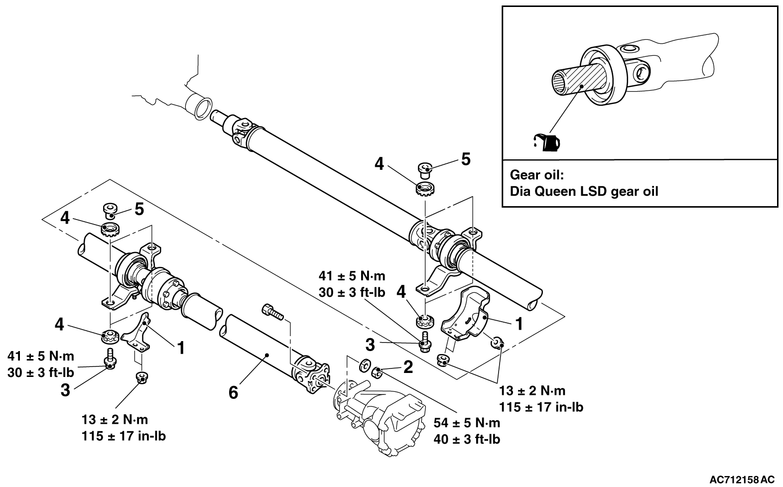
Your shaft won’t just slide out like a drawer. It’s press-fitted, coupled, sealed, and corroded into position. You need to follow the exact sequence. Skip one step and you’ll spend hours fighting seized metal.
Disconnect the Intermediate Shaft First
Start at the coupling between your intermediate shaft and transmission. Loosen all coupling bolts by two full turns. Don’t remove them yet. Leave two bolts at each end finger-tight. This stops rotation once you tackle the main propeller nut.
Now remove four coupler bolts. This separates the intermediate shaft from your transmission. Mark the coupling faces with alignment paint before you separate them. You’ll need these marks later for reassembly.
Remove the Propeller Assembly
Cut through your rope guard with bolt cutters. Replacing it costs less than working around it.
Remove the propeller cone, key, and retaining nut. Use a paint pen to mark a reference line across the shaft and propeller hub. This shows exact positioning for the new installation.
Rig support slings from your poop bollards or stern cleats. Chain blocks work best. They hold 500+ pounds steady while you work underneath. Position the support under your propeller hub.
For inboard setups: Remove the cotter pin first. Then back off the thick nut. Leave the thin nut threaded two turns onto the shaft. This protects threads during pressing.
Thread your propeller puller onto the hub. Tighten it bit by bit. Fifteen minutes of steady pressure beats 3 hours of hammering. The propeller breaks free from its taper seat with a sharp crack. Lower it using your support rigging.
Extract the Tail Shaft
Drain all stern tube oil into a catch pan. Slack the aft stern tube seal by loosening its compression nuts three full turns. Remove the forward seal. Unbolt the gland housing and slide it forward on the shaft.
Pull the tail shaft straight back through the stern tube. You need two people for this job. One guides from inside. One pulls from the swim platform.
Seized shaft? Stop pulling. Pour penetrating oil into both seal openings. Wait 24 hours. Use a hydraulic jack against the coupling face to break the corrosion bond. Push the shaft inward first into your intermediate bearing space. Then withdraw it.
For bad corrosion, you need to cut an access panel in your hull. Mark your cut line 8 inches aft of the stern tube. This gives clearance to slide the shaft inward before pulling it out.
Inspect the taper area right after removal. Look for cracks, scoring, or discoloration. Dark patches show poor bearing contact. These spots corrode fastest during service.
Shaft Alignment: Critical Procedure for Success
Misalignment destroys more boat propeller shafts than corrosion and impact damage combined. A gap of just 0.010 inches forces your cutlass bearing to absorb pressures beyond its design limits. The bearing overheats. The stern tube seal leaks. Your coupling bolts loosen from vibration. All because two metal surfaces don’t line up right.
Industrial data proves the cost. One paper mill corrected shaft misalignment and cut energy use by 30%. A manufacturing plant switched to laser alignment tools and reduced motor failures by 40%. Your boat operates under the same physics. Poor alignment burns fuel. It kills bearings in half their rated lifespan. It creates vibration that cracks fiberglass.
The Dial Indicator Method That Works
Mount your dial indicator on the shaft coupling face. Rotate the shaft by hand through four positions: top, right, bottom, left. Record each reading. Repeat the full rotation three times. Your numbers should match within 0.001 inches. Getting different readings? Check for soft foot—uneven mounting that throws off your alignment base.
The rim-and-face technique measures both angular and offset misalignment at once. Position one indicator on the coupling rim. Mount the second on the coupling face. Rotate together. Face readings show angular error. Rim readings show parallel offset. Both must fall within tolerance.
Laser Systems Beat Guesswork
Laser alignment tools measure down to thousandths of an inch. They give you real-time feedback as you adjust. No math required. The screen shows which direction to move and by how much.
|
Method |
Precision |
Best Use Case |
|---|---|---|
|
Dial indicators |
±0.002 inches |
Budget builds, experienced mechanics |
|
Laser systems |
±0.0005 inches |
Professional shops, first-time alignment |
One petrochemical facility stopped a major shaft failure by catching a 0.008-inch coupling gap during routine checks. Their laser system flagged the issue before it destroyed a $15,000 bearing.
The Step-by-Step Adjustment Process
Check soft foot first. Place feeler gauges under each engine mount. Loosen all mounting bolts. Tighten them bit by bit in a star pattern. Measure again. Any gap over 0.002 inches needs shimming.
Measure your initial alignment. Document everything. Make one adjustment at a time. Most moves are 0.005-inch changes on the mounting shims. Re-measure after each change. This takes patience. Rushing makes things worse.
Account for thermal growth if your engine runs hot. Inboard diesels expand during operation. Align them a bit offset cold. They’ll settle into perfect alignment at operating temperature. Check your engine manual for thermal expansion specs.
Check your final alignment with both vertical and horizontal measurements. Most marine drive shafts need under 0.003 inches total runout. Lock down all coupling bolts to manufacturer torque specs. Run a vibration analysis before and after. Good alignment drops vibration readings by 60-80%.
The laser alignment market hit $351.8 million in 2021. It’s projected to reach $453.2 million by 2025. That growth shows one thing: pros trust precision tools over old methods. Your shaft alignment decides if your new installation lasts two seasons or twenty.
Installing the New Propeller Shaft
Your new shaft waits on the workbench. Clean metal. Perfect taper. No corrosion. Install it right, and you get smooth cruising. Mess it up, and you’re looking at expensive repairs.
Prepare the Shaft and Stern Tube Path
Clean your stern tube bore with brake cleaner and lint-free rags. Remove every trace of old packing, corrosion, and salt deposits. Run a flashlight beam through the tube. You need glass-smooth walls for your cutlass bearing to seat right.
Wrap protective padding around the shaft’s bearing contact areas. Use clean shop towels secured with electrical tape. This stops scratches during insertion. One gouge in the bearing surface creates a leak path. That leak kills your seal within weeks.
Cover the entire shaft length with marine grease. This isn’t optional. The grease helps the shaft pass through the stern tube. It also protects against flash corrosion before you seal everything up.
Insert the Shaft Through the Stern Tube
Position two people for this job. One guides from inside the hull. One pulls from outside at the swim platform. Thread the shaft through the stern tube opening. Go slow. Keep it centered. Dragging across the tube edges damages both surfaces.
Watch your cutlass bearing zone as the shaft passes through. Stop every 12 inches to check alignment. The shaft should glide with steady pressure. Feel resistance? Stop. Back out and inspect for obstructions.
Push the shaft forward. The coupling face should sit flush with your intermediate shaft coupling. Don’t force the final positioning yet. You’ll fine-tune alignment in the next step.
Install the Cutlass Bearing
Your cutlass bearing needs a press-fit into the strut housing. The ABYC P-6 standard calls for 0.001-0.003 inches of interference fit. Anything looser spins in the housing. Anything tighter cracks the rubber.
Use a hydraulic or arbor press for installation. Coat the bearing exterior with marine grease before insertion. This cuts friction. It also stops the rubber from tearing during the press operation.
Press until the bearing seats flush with the housing face. Test for binding by rotating the shaft by hand. Smooth rotation means you installed it right. Any catching or resistance means misalignment.
Seal the Stern Tube
Use marine-grade sealant around the stern tube where it meets the hull. Products like Soflex or Fixte flexible adhesive create waterproof bonds that flex with hull movement. Work the sealant into gaps using a putty knife.
Create an epoxy gasket at the coupling-to-hull interface. This holds alignment and stops water migration. Mix your epoxy per manufacturer instructions. Put a continuous bead around the entire coupling perimeter.
Install new stern tube seals at both forward and aft positions. Tighten compression nuts in a cross pattern. Go slow. Torque to manufacturer specs—usually 15-20 ft-lbs for standard gland nuts.
Reconnect the Shaft Coupling
Align your coupling faces using the reference marks you made during removal. The sag and gap method verifies positioning. Measure the gap at top, bottom, and both sides. All readings should match within 0.003 inches.
Thread coupling bolts finger-tight first. Install them in a star pattern. This spreads clamping pressure out. Torque each bolt in three stages: 30%, 60%, then 100% of final spec. This stops the coupling faces from warping.
Run a shaft jack-up test after bolting. Lift the shaft with a hydraulic jack positioned under the coupling. Go easy. Movement over 0.005 inches means your engine mounts need adjustment.
Mount and Secure the Propeller Hub
Clean both the shaft taper and propeller hub bore with acetone. Put Prussian Blue dye on the shaft taper surface. Mate the propeller hub flat and rotate it 180 degrees three times. Remove and inspect the blue transfer pattern.
You need 70-80% contact for a good bed. See less? Put lapping compound on the taper. Install the propeller with one nut. Rotate it 180 degrees 10-12 times. Clean and re-check with Prussian Blue. Aim for 85-90% metal-to-metal contact.
Slide the propeller onto the shaft. Line up your match marks from removal. Install the key with light oil lubrication. Just oil. Never use grease or anti-seize on propeller keys. They loosen under vibration.
Stack your hardware in this exact order: thick washer first, Belleville washer with cupped edges touching the thick washer, small thick washer last. Thread on the thin nut and torque to 75% of full spec. Then install the full-height nut and torque to 55 ft-lbs for Flo-Torq SSR HD systems.
Wedge a wood block between a propeller blade and the anti-ventilation plate. Use a hex wrench to get the right torque. Add the half-height locknut and tighten it down. Insert a stainless steel cotter pin—never brass—through the drilled hole. Bend the pin ends over the nut.
Your new marine drive shaft is installed. Fill the stern tube with marine oil. Run the engine at idle for 5 minutes. Check for leaks, odd vibration, or noise. Normal operation means you did it right.
Post-Installation Testing and Break-In
Your new shaft sits aligned. Seals look tight. Couplings torqued to spec. Here’s what separates careful mechanics from careless ones: the break-in protocol.
Rush this phase and you’ll destroy bearings that should last 10 years. I’ve seen boat owners fire up their engines to full throttle within minutes of installation. Their cutlass bearings failed within the first season. The raceway surfaces never got conditioned. The grease never settled into the right position between metal surfaces.
The Progressive Speed Protocol
Start with five one-minute cycles at 33% maximum RPM. Rest two full minutes between each cycle. These short bursts help your bearings start polishing the raceway surfaces. No excessive heat builds up this way.
Move to 66% max RPM for another five cycles. Same timing: one minute running, two minutes rest. Reach your target speed within 20 seconds of each cycle start. Don’t creep up. That generates more friction heat than a quick acceleration to speed.
Finish with five cycles at 100% max RPM. Then run two continuous 30-minute sessions at your normal operating speed. Five-minute rest between those long runs. Critical rule: Put zero load during this entire break-in sequence. No pulling skiers. No cargo weight. Just the engine spinning your shaft against water resistance.
Temperature Monitoring That Matters
Mount your temperature sensor on the stern tube housing near the cutlass bearing. Housing readings run 10-15°F cooler than actual bearing temperatures. Track this difference as heat builds up.
Stop right away if temperature exceeds 140°F (60°C). Small bearings stabilize within 20 minutes. Your marine drive shaft bearing takes several hours. Normal operating range sits 10-40°C above room temperature. You should hit steady state within 1-2 hours after startup.
A mild initial temperature rise is normal for grease-lubricated bearings. Friction between grease and metal creates heat during the first few cycles. But watch for these danger signs:
-
Temperature keeps climbing without leveling off
-
Rapid spikes during speed increases
-
Final temperature exceeds 100°C
These patterns point to installation problems. Check for insufficient clearance, wrong lubricant type, or a misaligned coupling creating friction loads.
Sound Analysis During Break-In
Run each speed cycle with your engine compartment open. Listen for odd bearing sounds through the hull.
|
Sound Pattern |
What It Means |
Your Response |
|---|---|---|
|
Buzz, roar, or howl |
Dust contamination or damaged raceway surfaces |
Stop right away |
|
Screech or grinding |
Damaged balls/rollers, poor fit, or deformed raceway |
Stop right away |
|
Crunch or chatter (felt through the hull) |
Raceway damage or contamination |
Stop right away |
|
Irregular tinkle sounds |
Minor dust presence |
Investigate but continue monitoring |
Place your hand on the stern tube housing during idle. Feel for vibration patterns. Smooth, even humming means good installation. Pulsing, chattering, or irregular vibration means coupling misalignment or bearing contact issues.
The Break-In Science
This gradual speed progression does three critical things. It smooths and polishes raceway surfaces no matter what lubrication you use. It settles grease into the right position between balls and raceways. This prevents grease fling at operating speeds. It conditions the metal surfaces to reduce operating temperature for the bearing’s entire service life.
Proper break-in extends your cutlass bearing lifespan by 40-60% compared to going full-throttle right away. The time you invest pays back through years of smooth, quiet operation. Plus, you get longer maintenance intervals.
Common Mistakes and How to Avoid Them
Most shaft replacements fail because boat owners skip the boring parts. They rush alignment. They eyeball measurements. They trust their gut over their dial indicator. Then they wonder why their $2,500 repair sounds worse than the original problem.
Forcing a Seized Shaft Through the Stern Tube
Corrosion welds your old shaft to the cutlass bearing. You pull harder. The shaft refuses to budge. So you grab a sledgehammer and start beating. Stop.
That brute force approach cracks your stern tube bronze. Those cracks cost $1,800 to repair—more than the entire shaft replacement job.
The fix: Soak everything in penetrating oil for 48 hours minimum. Not 2 hours. Not overnight. Two full days. Heat the stern tube housing with a propane torch—15-second bursts. Use a hydraulic jack against the coupling face to push the shaft inward first. This breaks the corrosion bond. Then pull it straight back through the tube.
Installing Cutlass Bearings Without Proper Interference Fit
You measure the bearing outer diameter. You measure the strut housing bore. The bearing slides in by hand. Perfect, right? Wrong.
Hand-fit bearings spin inside the housing within weeks. They chew up the bronze. They create vibration that destroys your new shaft seal.
The fix: ABYC P-6 standard requires 0.001-0.003 inches of interference fit. The bearing diameter needs to be 0.001-0.003 inches larger than the housing bore. Use a hydraulic press for installation. Never hammer it in. Press until the bearing face sits flush with the housing end. Test by trying to rotate it by hand—it shouldn’t move at all.
Skipping the Prussian Blue Taper Contact Test
You clean the shaft taper. You clean the propeller hub bore. You slide the prop on and torque the nut down. Done in 10 minutes.
Poor metal-to-metal contact loosens the propeller under load. It hammers the keyway. The key shears and your prop falls off at 3,000 RPM.
The fix: Put Prussian Blue dye on the shaft taper before test-fitting. Install the propeller and rotate it 180 degrees three times. Remove it and check the blue transfer pattern. You need 70-80% initial contact minimum. See less? Use lapping compound to bed the surfaces. Repeat until you hit 85-90% contact. This takes 30-45 minutes but prevents $800 emergency haul-outs.
Reusing Old Coupling Bolts
Those coupling bolts look fine. No visible rust. Threads still turn smooth. Why spend $40 on new hardware?
Marine coupling bolts stretch under torque cycling. The metal gets tired from vibration loads. Reused bolts loosen during your first long cruise. Loose couplings destroy shaft alignment and eat cutlass bearings.
The fix: Replace every coupling bolt, washer, and lock nut during shaft installation. Use marine-grade 316 stainless hardware. Torque them in three stages using a star pattern. Final torque needs to match your coupling maker’s spec—140-165 ft-lbs depending on shaft diameter. Lock-wire the final parts together. Or use prevailing-torque locknuts rated for marine vibration.
Maintenance Tips to Extend Shaft Life
Your propeller shaft doesn’t ask for much. Regular care beats expensive replacement.
Inspection Protocol That Works
Check your shaft once a month during boating season. Focus on two failure modes: deformation and corrosion. Run your hand along the entire shaft length. Feel for raised areas, pits, or rough patches. A smooth surface under your palm means healthy metal. Any texture change signals trouble.
Look for bending with a straight edge held against the shaft. See a gap between the edge and shaft surface? That’s too much. Warping shows up as uneven wear patterns on your cutlass bearing. One side worn more than the other? Your shaft bent under stress.
Salt deposits speed up corrosion. Rinse your stern tube area with fresh water after every saltwater trip. Use a pressure washer on low setting. Debris packed around shaft seals holds moisture against metal surfaces. That moisture turns into rust.
Lubrication and Analysis
Your stern tube oil tells stories about shaft condition. Change it per your engine maker’s schedule. That’s about every 100 operating hours. Send samples to a marine oil analysis lab twice per season. They’ll spot metal particles before you hear grinding noises.
Metal content above 50 parts per million means bearing wear. Bronze particles point to cutlass bearing breakdown. Steel particles signal shaft surface damage. Catch these problems soon and you replace a $180 bearing instead of a $2,500 shaft.
Put marine grease on exposed shaft sections during winter storage. This stops flash corrosion during humid months.
Alignment Verification
Check shaft alignment every six months. SKF bearing research shows misalignment causes 50% of marine drive failures. Mount your dial indicator and rotate the shaft through four positions. Record readings at each point.
Readings varying more than 0.003 inches mean your engine mounts shifted or your hull flexed. Re-align before damage spreads. Good alignment cuts bearing replacement by 60-70%.
Calling a Professional Marine Mechanic
Sometimes you need to stop turning wrenches and pick up the phone.
DIY vs. Professional Work
Shaft replacement needs a pro. Specialized equipment makes the difference. Welding a cracked coupling? That’s pro work. Rewinding an inboard motor after electrical failure? Same deal. Fabricating custom stern tube repairs? You need naval architecture skills and certified facilities for these jobs.
The average marine mechanic earns $25.30 per hour ($52,620 each year). Water transportation specialists make $30.93 per hour. That premium pays for skills you can’t learn from YouTube.
Emergency repairs cost 30% more than planned maintenance. Tow bills average $750 before a mechanic touches your boat. Unplanned downtime eats up to 20% of annual revenue for commercial operators. These numbers show why 23,230 motorboat mechanics nationwide stay busy. The U.S. faces skilled labor shortages in shipyards, but mechanics have plenty of work.
Signs You Need Professional Help
Your engine vibration sensors show odd readings. Call a pro. The aging U.S. fleet means repair frequency jumps above 80%. Maintenance catches problems before major failures. Routine data checks show anomalies? Time for an expert to investigate.
Warranty and insurance often require certified mechanics. Professional service contracts cut emergency repair costs by 30%. They do this through better maintenance schedules. The U.S. ship repair market hit $11.94 billion in 2024. It projects to $13.13 billion by 2032. Marine systems keep getting more complex. That growth shows it.
Look for shops with a 30% annual expense ratio. They should offer same-day service on 10% of jobs. Certified facilities handle noise and emissions rules. The global ship repair market reached $24.8 billion in 2024. It’s heading toward $36.2 billion by 2034. Pick mechanics who keep up with these growing technical needs.
Conclusion
Replacing a boat propeller shaft isn’t as scary as it looks. Break it down into simple steps—check everything first, align the shaft right, then install it—and you’ve got a weekend project. This saves you $1,500+ and teaches you how your boat’s drivetrain works.
The real win? You’re no longer waiting on boatyard schedules. You won’t wonder if that mechanic aligned your marine drive shaft right. You’ve got the knowledge. You’ve got the confidence. Diagnose problems before they get worse. Do your own maintenance. Keep your boat running well all season long.
Start with a full inspection this weekend. Measure that shaft runout. Check for play in the cutlass bearing. Then decide if you need a minor fix or a full replacement. Your boat will thank you. Your wallet will too. Catch issues now before they turn into major failures out on the water.
Ready to tackle the job? Gather your tools. Order quality replacement parts. Set aside a full day. You’ve got this.